
However, our system also allows multiple kill switches to be installed and the fitment of two external ‘kill’ buttons, one on each side of a race car, has become popular safety feature.Īll switches/push- buttons are connected to the Isolator via light weight, low current wiring and configured such that the Battery Isolator will automatically turn off should any of the wire connections become broken in a catastrophic accident. The Isolator can be controlled by any number of switches although the usual configuration is one internal on- off switch and one external kill button. This latter method of engine kill means that the XR is smaller and lighter than the GT and incorporates a sealed, circular connector. The GT unit has a 40A switched power output which can be used as the main power feed for most ECUs and/or ignition systems while the XR unit outputs a low current, ‘Ignition Off’, signal which is compatible with most motorsport ECUs and PDMs.
CAR BATTERY ISOLATOR RELAY WIRING DIAGRAM HOW TO
9 Pics about How to wire a baldor 元514 to a 6 pole drum switch single phase 115 : Installing a kill switch on the starter battery bank - School Bus, Battery isolator help - TeamTalk and also Installing a kill switch on the starter battery bank - School Bus. However, the main difference between these two units is the method used to stop the engine. How to wire a baldor 元514 to a 6 pole drum switch single phase 115. 12V 140 Amp Dual Battery Smart Isolator & ATV UTV Wiring Kit by KeyLine Chargers - Voltage Sensitive Relay for RV Marine Car Vehicles Truck Caravan Off-road. Connect one of the big contacts to the main battery. Remove power from the 2 small contacts and the 2 big contacts will be disconnected. Give the 2 small contacts positive and negative, and the 2 big contacts will be connected. The first breaks the connection between the negative side of the vehicle’s battery from chassis/earth, thereby isolating the battery power from all electrical circuits, while the second cuts power to the engine electrics and thereby stops the engine from running.Ĭartek produces two types of Battery Isolator GT and XR.īoth systems isolate the battery from all electrical circuits, in accordance with FIA requirements, by disconnecting the negative terminal of the battery from chassis/earth. Do you have any wiring diagrams on how to use this for a dual battery setup - by Audio (Enola) A.

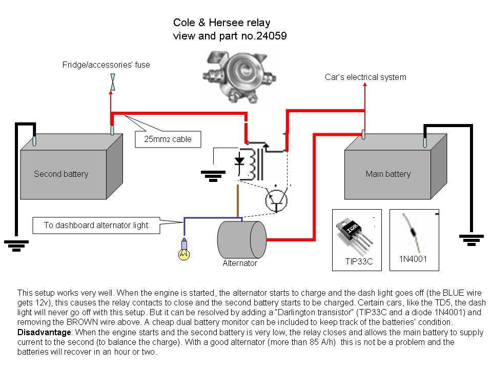
Output from the second battery positive post will then go to the items you want to power. The second battery will attach to the 2 via a circuit breaker that is rated appropriately for the battery.

The main battery will connect to position one and the alternator to the A post. The Solid State Isolator contains two isolation circuits. For your battery isolator similar to DW08771, you will have connection posts for each battery and for an alternator.


 0 kommentar(er)
